The configuration tasks you need to perform depends on how your network is configured. There are four example configurations provided here. These particular physical link stations support the exchange of information between Blueworx Voice Response and any application running on a System/370, System/390, or AS/400 processor that communicates through a 3270 data stream using LU 2 protocols.
If your network is not similar to one of the examples, use the information in the System Management Guide; Communications and Networks, to determine how to define it.
Example SNA link station A
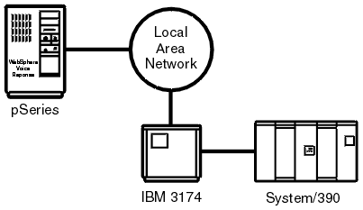
In example A (shown in Figure 1), a pSeries computer is connected on a token-ring LAN, through an IBM 3174 Establishment Controller, to an IBM System/370, System/390, or AS/400.

This procedure describes how to connect the pSeries computer to a System/370 or System/390 in the configuration shown in Figure 1.
- On the System/370 or System/390: Create an entry in the VTAM definition file for each downstream physical unit (DSPU): the IBM 3174 and the pSeries computer.
- Create a logmode entry.
- On the pSeries computer: Use xsnaadmin to configure the token-ring link station (see Defining a link station using SNA).
- Configure the 3174 to include the address (or alternate address) of the token-ring adapter in the pSeries computer.
- Start Communications Server for AIX.
This procedure describes how to connect the pSeries computer to an AS/400 in the configuration shown in Figure 1.
- On the AS/400: Create a network description object, a controller description object, and a device description object (one for each terminal).
- On the pSeries computer: Use xsnaadmin to configure the token-ring link station (see Defining a link station using SNA).
- Configure the 3174 to include the address (or alternate address) of the token-ring adapter in the pSeries computer.
- Start Communications Server for AIX.
Example SNA link station B
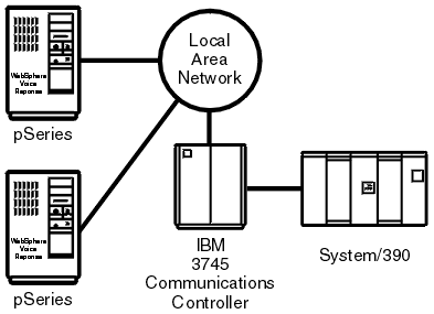
In example B (shown in Figure 2), two pSeries computers are connected on a token-ring LAN, through a communication controller, to an IBM System/370 or System/390. You can also attach the pSeries computers on the LAN to an AS/400. In this case, the communication controller is internal to the AS/400.

This procedure describes how to connect the pSeries computer to a System/370 or System/390 in the configuration shown in Figure 2.
- On the System/370 or System/390: Create an entry in the VTAM definition file for each downstream pSeries computer.
- Create an NCP for the communication controller, or alter any existing NCP to reflect the additional DSPUs.
- Create a logmode entry.
- Reinitialize the communication controller.
- On the pSeries computer: Use xsnaadmin to configure the token-ring link station (see Defining a link station using SNA).
- Start Communications Server for AIX.
This procedure describes how to connect the pSeries computer to an AS/400 in the configuration shown in Figure 2.
- On the AS/400: Create a connection definition object, a controller description object, and a device description object (one for each logical device).
- On the pSeries computer: Use xsnaadmin to configure the token-ring link station (see Defining a link station using SNA).
- Start Communications Server for AIX.
Example SNA link station C
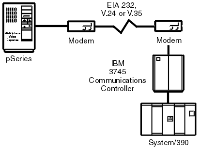
In example C (shown in Figure 3), a pSeries computer is connected, using an SDLC connection through a communication controller, to an IBM System/370 or System/390. You can also attach the pSeries computer to an AS/400 using an SDLC connection. In this case, the communication controller is internal to the AS/400

This procedure describes how to connect the pSeries computer to a System/370 or System/390 in the configuration shown in Figure 3.
- On the System/370 or System/390: Create an NCP for the network controller, or alter any existing NCP to reflect the additional DSPUs.
- Create a logmode entry.
- Reinitialize the communication controller.
- On the pSeries computer: Use xsnaadmin to configure the SDLC link station (see Defining a link station using SNA).
- Start Communications Server for AIX.
This procedure describes how to connect the pSeries computer to an AS/400 in the configuration shown in Figure 3.
- On the AS/400: Create a connection definition object, a controller description object, and a device description object (one for each logical device). Create a logmode entry.
- On the pSeries computer: Use xsnaadmin to configure the SDLC link station (see Defining a link station using SNA).
- Start Communications Server for AIX.
Example SNA link station D
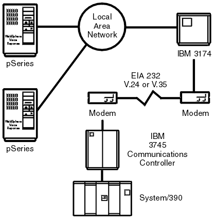
In example D (shown in Figure 4) up to four pSeries computers on a token-ring LAN are connected to an IBM System/370 or System/390, using an SDLC connection through an IBM 3174 and a communication controller.

This procedure describes how to connect several pSeries computers to a System/370 or System/390 in the configuration shown in Figure 4.
- On the System/370 or System/390: Create an entry in the VTAM definition file for each downstream physical unit: the SDLC link station, the IBM 3174, and the pSeries computers.
- Create an NCP for the communication controller, or alter any existing NCP to reflect the additional DSPUs.
- Create a logmode entry.
- Reinitialize the communication controller.
- On the pSeries computer: Use xsnaadmin to configure the token-ring link station (see Defining a link station using SNA).
- Configuring the 3174: Configure the 3174 to include the address of the token-ring adapter in the pSeries computer.
- Start Communications Server for AIX.