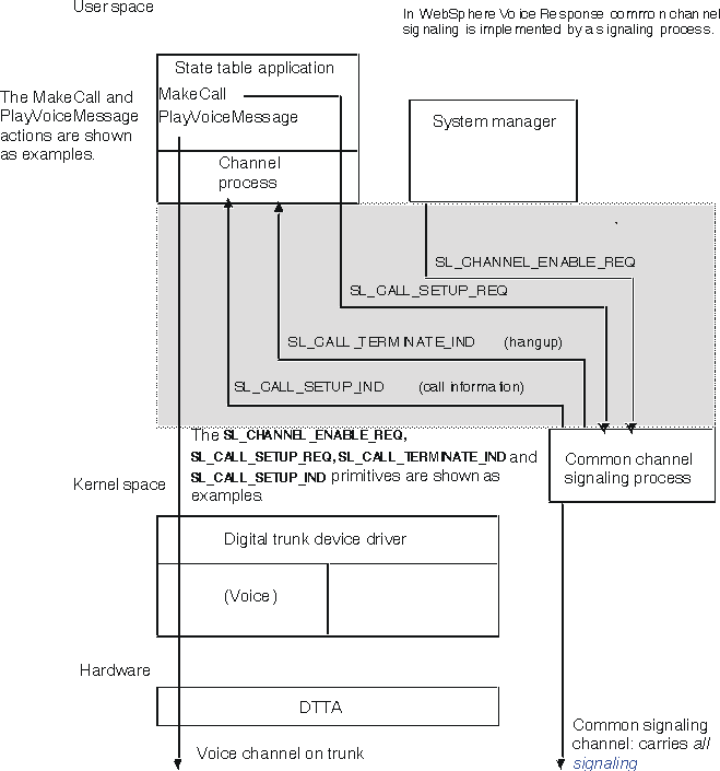
Figure 1 shows the system components involved in processing a voice application when using common channel signaling. Telephony actions, such as MakeCall, result in signaling information being sent to the signaling process across the signaling interface. The signaling process sends the information to the lower-level device driver, which translates it into the protocol being used on the common signaling channel. Voice processing actions, such as PlayVoiceMessage, result in audio signals being sent on the voice channel.
In addition, the signaling process provides additional signaling information, such as call information when the call is received, and hangup notification when the call is terminated by the network. This information is received by the signaling process and sent to the channel process across the signaling interface.
Outgoing call setup
State table MakeCall actions are interpreted by the channel process, and passed to the signaling process, which performs the signaling required. When the signaling is complete, the signaling process returns control to the channel process, which maps the result into an edge which is returned to the state table.
Incoming call setup
Incoming calls are detected by the signaling process, which notifies Blueworx Voice Response, and therefore the channel process manager. Common channel signaling protocols usually include call information in the incoming call notification. The signaling process passes this information to Blueworx Voice Response at the same time it reports the incoming call. The call information is available to the channel process manager and channel process from the signaling interface. The channel process manager determines which state table to execute, and a channel process is allocated to run the state table.
Call clearing initiated by Blueworx Voice Response
State table TerminateCall actions are interpreted by the channel process, and passed to the signaling process, which performs the signaling required. When the signaling is complete, the signaling process returns control to the channel process, which maps the result into an edge that is returned to the state table.
Call clearing initiated by the network
Incoming clear notifications are received from the network. The signaling process then notifies the Blueworx Voice Response system of the event. In this case it is not necessary for the digital trunk device driver to monitor the voice energy level on the line, to detect when the caller has hung up. Clear notification over the common channel signaling link is also much quicker than monitoring voice energy, which means that there is a shorter delay before the channel can be reallocated for a new caller.