How to install the TR114 card.
- Turn off the computer.
- Remove the bracket from a vacant PCI slot.
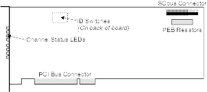
- Remove the PEB resistor bank from the TR114 card (see Figure 1)
- Insert the TR114 firmly into the slot while holding the card at each top corner.
- Screw the TR114 card's mounting bracket to the computer's frame.
- Connect the SCbus interface by locating the 26-pin SCbus connector
on the TR114 card (see Figure 1)
and inserting the cable. Note: Cable length should not exceed 21"; maximum number of SCbus connectors is 21; distance between connectors should not be less than 1.0".
- Turn on the computer.
- Check that all the LEDs come on at once, stay on momentarily and then go off in pairs. Once the computer has booted up, the LEDs should appear to flash at random.
Figure 1. Layout of the TR114 +P16S Card


The SCbus will operate in SCSA mode and the PEB resistor bank should therefore be removed from the card.
For further information on card settings see Brooktrout Technology: TR114 PCI Digital Hardware Guide
Warning
Electrostatic Discharge (ESD) can cause immediate or latent damage to Integrated Circuits. In order to minimize ESD you should wear an antistatic wrist strap whose lead has been clipped onto the metal chassis of the computer or, at the very least, touch the computer's chassis before you handle the fax card, in order to discharge any static electricity you may be carrying.