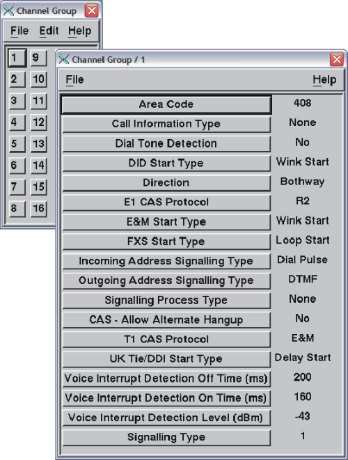
- At the Welcome window, select Configuration —> System Configuration —> Change.
- Click Channel Group.
- Displaying the Channel Group parameters: Open the
first channel group to be defined.
The system displays the existing values of the parameters that apply to all channels assigned to this group.

- If you have specified a channel associated signaling protocol, go to Step 7.
- Common Channel Signaling protocols: If you have specified
a common channel signaling protocol (ISDN or a custom-written signaling
process), set the parameters as shown in Table 1.
Table 1. Common channel signaling parameters. This table describes the value to set for each common channel signaling parameter.
Parameter
Setting
Call information type
Set this parameter to Signaling Process.
Signaling process type
Set this parameter as appropriate:
- The ISDN... value for your ISDN protocol
- User1 through User19: the name of your custom-written signaling process.
Area code
Set this to a 1- to 6-character value.
In the event that called number information is not received, the Area Code value is used with the Phone Number parameter of the channel, to create the channel identification to be used to find the application profile.
- Go to Anything else?
- Channel Associated Signaling Protocols: Click the numbered Signaling Type that you defined when following the procedure Defining signaling types. Do not click any of the named signaling types because you cannot edit them later.
- Click the start type, using the parameter appropriate to your
protocol:
- T1 CAS Protocols:
- DID Start Type
- FXS Start Type
- E&M Start Type
- E1 CAS Protocols:
- UK Tie/DDI Start Type
- FXS Start Type (Loop Start only)
- T1 CAS Protocols:
- Depending on what you decided in Configuring Blueworx Voice Response to get the called and calling numbers, follow the steps in one of the following tables:
| Parameter |
Values for fixed length incoming register signaling |
Values for feature group D incoming register signaling |
|---|---|---|
| Call information type |
Set this parameter to Register. |
Set this parameter to Register. |
| Incoming address signaling type |
Set this parameter to MFR1, DTMF, or Dial Pulse, depending on the capabilities of your switch. Note that the incoming and outgoing address signaling types are normally the same. |
Set this parameter to MFR1. |
| Signaling process type |
Set this parameter to None. |
Set this parameter to None. |
| Area code |
Set this to a 1- to 6-character value. |
Set this to a 1- to 6-character value. |
| In the event that called number information is not received, the Area Code value is used with the Phone Number parameter of the channel, to create the channel identification to be used to find the application profile. |
||
| Call information type |
Set this parameter to None, which is the default. |
|---|---|
| Signaling process type |
Set this parameter to None, which is the default. |
| Area code |
Set this to a 1- to 6-character value. In the event that called number information is not received, the Area Code value is used with the Phone Number parameter of the channel, to create the channel identification that is to be used to find the application profile. |
| Parameter |
Values SMSI, SMDI or VMS |
Values for ACL |
Values for CallPath_SigProc |
|---|---|---|---|
| Call information type |
Set this parameter to Signaling Process. |
Set this parameter to Signaling Process. |
Set this parameter to Signaling Process. |
| Signaling process type |
Set this parameter to SMSI/SMDI/VMS. |
Set this parameter to ACL. |
Set this parameter to User1. |
| Area code |
Set this parameter to the 1- to 6-character prefix that is to be used for all channels in the channel group. The area code is concatenated to the dialed number sent on the exchange data link. |
Set this parameter to the 1- to 6-character prefix that is to be used for all channels in the channel group. The area code is concatenated to the dialed number sent on the exchange data link. |
Set this parameter to the 1- to 6-character prefix that is to be used for all channels in the channel group. The area code is concatenated to the dialed number sent on the exchange data link. |
Anything else? Review the explanations of the remaining parameters that are listed in Channel parameter group or in the online help. If any of the values are not suitable for use with your switch, change them.
Although the System Configuration window is still displayed, the system has saved the parameter values for the channel group.